English


Search
Vacuum stability becomes a lamination problem when the system cannot remove air quickly enough or maintain consistent negative pressure throughout the critical processing window. The vacuum valve is one of the key interfaces in this system because its flow path, sealing performance, connection size, and temperature resistance influence how efficiently air travels from the laminate to the pump.
For glass processors, the correct valve should therefore be selected according to the complete vacuum circuit rather than simply by matching the tubing connection.
A laminated-glass assembly contains interfaces where air can become trapped between glass and polymer layers.
During vacuum-assisted processing, that air needs to be evacuated before the interlayer becomes sufficiently soft to encapsulate remaining voids.
Stable vacuum conditions provide two important functions: they promote effective de-airing and maintain compression during consolidation.
If the vacuum fluctuates excessively, the laminate may experience inconsistent pressure. The resulting defects can include bubbles, incomplete contact, localized haze, and inconsistent bonding.
Vacuum instability can originate from several parts of the system.
Common causes include:
leaking vacuum bags;
damaged membranes;
poor perimeter sealing;
restricted tubing;
undersized valves;
leaking connectors;
insufficient pump capacity;
excessive distance between the extraction point and laminate.
This makes troubleshooting more complex than simply checking whether the pump is running.
A vacuum pump can be functioning correctly while the actual evacuation rate at the laminate remains inadequate because of restrictions elsewhere in the circuit.
Yes.
The valve forms part of the airflow path. If its internal passage is too restrictive, it can limit how quickly air leaves the vacuum chamber or bag.
This becomes particularly important with large laminated panels or systems using multiple extraction points.
A useful engineering concept is that the pump's nominal capacity is not necessarily equal to the airflow available at the laminate.
Actual performance depends on:
pump capacity + tubing diameter + valve flow path + connector resistance + leakage + system geometry.
The smallest or most restrictive component can become a practical bottleneck.
The most important parameters include:
| Parameter | Why it matters |
|---|---|
| Port diameter | Influences airflow restriction |
| Internal flow path | Determines resistance to air movement |
| Sealing system | Affects vacuum leakage |
| Temperature rating | Important during heated lamination |
| Connection type | Must match tubing and equipment |
| Material compatibility | Prevents degradation during processing |
| Maintenance requirements | Influences long-term reliability |
A vacuum valves selection should therefore be based on process requirements rather than nominal size alone.
An undersized valve may slow evacuation during the period when the largest volume of air needs to be removed.
This creates a potentially serious timing problem.
Suppose the laminate requires a certain amount of time to reach adequate de-airing, but the restricted valve extends that period significantly. If the interlayer begins to soften before enough air has been removed, residual air can become trapped.
The problem is not necessarily that the final vacuum level is too low. The problem may be that the system reaches that vacuum too slowly.
This distinction is important when troubleshooting production defects.
Yes.
Valve leakage can result from worn seals, damaged components, contamination, incorrect installation, or temperature exposure beyond the component's suitable operating range.
However, a suspected valve should always be tested as part of the complete circuit.
A leaking connector or damaged tube immediately upstream may produce symptoms that look like valve failure.
For production diagnostics, measuring pressure decay and isolating individual sections of the vacuum system is more reliable than replacing components randomly.
Optical defects are often attributed to the interlayer, but the vacuum process can be equally important.
If air remains between the glass and polymer during the early processing stage, the polymer may eventually encapsulate those voids.
This can produce bubbles or local optical defects that are difficult to correct after consolidation.
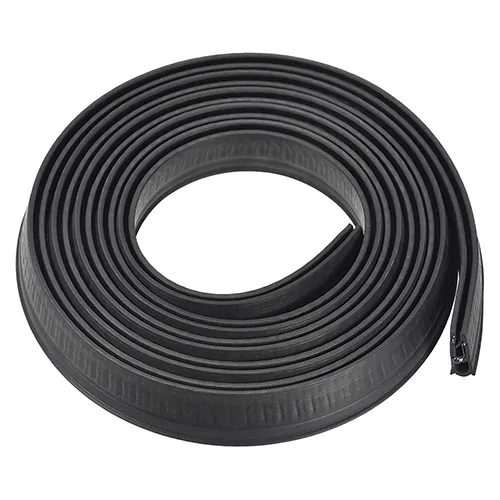
For this reason, sealant tape and vacuum valves should be considered together. The tape establishes the airtight perimeter, while the valve provides the controlled extraction path.
A failure in either component can affect the same final quality characteristic.
Not necessarily.
The objective is not simply to maximize negative pressure. The process needs an appropriate combination of vacuum level, evacuation rate, temperature, time, and pressure conditions.
Excessive or poorly controlled vacuum can also create process complications depending on the equipment and laminate construction.
The correct vacuum specification should therefore come from the validated process window for the interlayer and equipment.
Large panels may require greater attention to extraction-point location and airflow distribution.
If the vacuum connection is located too far from the most difficult-to-de-air region, air may have to travel a long path through a restrictive configuration.
Multiple extraction points can sometimes improve distribution, particularly for large or complex assemblies.
The design should consider the physical geometry of the laminate rather than treating every panel as a simple flat surface.
A systematic sequence is more efficient than changing several variables at once.
First, verify the sealing system. Then inspect tubing and connections. Next, test the valve and flow path. After that, evaluate pump performance.
If the vacuum system is stable but optical defects remain, attention can then shift toward glass cleanliness, interlayer storage, moisture, heating profile, and consolidation.
A glass interlayer should not be rejected solely because a laminate shows bubbles before the vacuum system has been verified.
There is no single universal value. The correct vacuum depends on the interlayer, equipment, bagging method, temperature profile, and validated processing window.
Possible causes include sealant failure, membrane damage, leaking valves, loose connections, restricted tubing, or component behavior changing with temperature.
A larger flow path can reduce restriction, but it will only improve evacuation when the rest of the system is appropriately designed.
Possible causes include an undersized valve, restricted tubing, excessive system volume, a weak pump, or leakage.
Vacuum control should therefore be approached as a complete engineering system. The valve is important, but its performance only becomes meaningful when considered together with sealing, tubing, pump capacity, and laminate geometry.